MagForce motor system installation
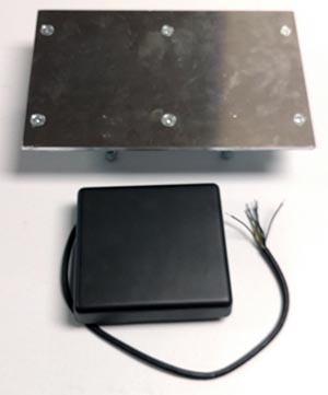
Chime Master intelliSwing MagForce™ swinging bell systems feature a unique touch-less, friction-less and nearly silent motor technology. A stationary drive module induces electro-motive eddy-current forces into a reactor plate mounted to the free swinging bell assembly. A wall mounted motion control panel intelligently experiments and quickly learns the unique physical properties of your bell then carefully manages the energy required for accurate ringing.
Mechanical considerations
All MagForce motors should be installed with modern ball bearing pillow block bearings on the A-stand pivots. Older sleeve bearings exceed the frictional allowances needed for automation.
Cranked head stocks
A cranked head stock, sometimes called a yoke, suspends the bell slightly below the center of gravity (CG). This configuration is often used to reduce the side loads to the tower when the bell is swinging. Because the CG of the bell is near the center of bearing rotation, the bell is also easy to swing. We want to size the motor for both the bell's weight and the CG effect, but you may have to reduce the motor power during programming to prevent the bell from going over the programmed swinging angle.
Straight head stocks
A straight head stock, especially when not incorporated with counterweight above the bell (with either a wooden head stock or additional iron weights), will require a powerful motor to swing the bell.
Mounting the stationary motor brick
The center of the motor should be mounted at a minimum 80% of the bell diameter down from the top of the bell. For straight yokes (and flying clappers), this will be the length of the reactor plate mounting arms.
Motors can be mounted above the bell (at the same radius from the pivot point) if the weight of the reaction plate is taken into consideration when designing the head stock crank depth. This will also slow the ringing tempo. Do not mount the motors above the pivot on existing cranked head stocks, the bell will not ring properly.
The motor should be mounted to a 1/4 to 3/8 inch aluminum plate when possible to serve as a heat sink. The plate can then be spaced out from the frame with threaded rod for positioning toward the reaction plate.
The motor induction housing should be painted with a polyurethane coating for UV resistance when used outside, and can be painted with the tower to match.
Mounting the reaction plate
The reaction plate should be centered vertically on the center line of the motor brick.
Securely fasten the reaction plate to the wheel when possible, centered on the stationary motor brick. There should be about a quarter-inch gap between them and the mounting design should be rigid enough that you cannot pull them together by hand. During operation, the plate will be magnetically attracted to the motor, and the rigidity is required for sufficient swinging torque.
Low current feedback connections
The motor control circuit needs some motion feedback from the bell to determine that it is swinging properly. We offer two types of feedback devices to accomplish this. The wiring requirements are the same for both. Four conductors of a telco or CAT5 cable usually suffice for this low current 12V signaling.
Precision rotary motion sensor (standard)
This option is used with a MagForce motor improved motion feedback. The rotary encoder is mounted to a non-moving part (like an A-stand) with pulleys and belt to sense the precise angular movement of the swinging bell axle. A separate logic translator is supplied in a weatherproof box and may be used as a junction box at the bell location.
There are four wires used in the encoder cable that connect to the translator:
Green to quadrature input A on the translator
Gray to quadrature input B on the translator
Brown to input +V on the translator (+5VDC)
White to input 0V on the translator
The translator outputs connect one to one to the motion controller sensor inputs: P (pulse), D (direction), + (positive power, +12VDC), - (negative power).
For rotary encoder systems, verify that the label on the CPU chip of the motor control system says "SENSOR." Use the rotary motor programming procedure and set the Transmission value to 22.8.
Proximity sensor
These sensors are not used in recent installations.
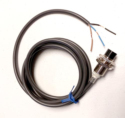
A three wire (60 inch cable) proximity sensor provides output when a bolt head or metal flag is about 1/4 inch away. Typically, a bolt is mounted to protrude from the bell wheel or head stock assembly. A stainless steel sheet metal flag is also supplied that can be mounted with dual adhesive foam tape or epoxy to the wheel or head stock.
The proximity sensor must be located at least 8 inches from the induction motor brick to prevent electromagnetic interference. It should also be far enough from the head stock pivot to sense small movements of the bell (5 degrees minimum). When the bell is at rest, the bolt or flag should be centered on the sensor.
For proximity sensor use, verify that the motor control computer chip is labeled "PERIOD."
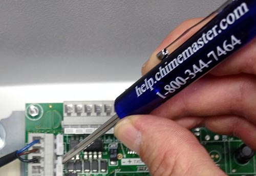
The cable on the sensor has three wires that connect to the sensor input of the motion control computer (use a small screwdriver to depress spring loaded contacts):
Blue (negative power) to - on the circuit board
Brown (positive power) to + on the circuit board
Black (sensor output) to D on the circuit board
If you use a cable with other colors to extend these wires, make note of the colors you splice together, so the connections to the control computer circuit board are correct.
System electrical connections
Downloadable riser diagrams (pdf suitable for 11x17 paper):
- 1-Phase, 1-Hammer, 1-intelliSwing MagForce linear motors
- 3-Phase, 1-Hammer, 1-intelliSwing MagForce linear motors
- 3-Phase, 1-Hammer, 3-intelliSwing MagForce linear motors
- 3-Phase, 2-Hammers, 2-intelliSwing MagForce linear motors
Power input
Chime Master must know definitively the available power for the bell system prior to quotation. You should have an electrician survey the power situation. We have had instances where three phase power entry boxes were used in buildings with only a single phase service.
Note that these diagrams are shown with 3 phase 208VAC power. This is the optimal situation for MagForce motors. When only single phase 230VAC power is available, motor capacitors are added to the motor control panel, and the overloads are rewired for single phase supply. In all cases, three power wires are always required from the control panel to the motor.
Three phase
Three phase power when available is preferred because a smaller motor may provide the needed torque, and also because the motor does not hum as loud as single phase systems. Three power input terminals will be labeled L1, L2 and L3 in the motor control box. Separate Chime Master relay panels will use only L1 and L2 (single phase) for the controls and clapper/hammer outputs.
Single phase
Two power input terminals will be labeled L1 and L2 for single phase motor control boxes. Internal connections to PCBs will use L1 and L3.
Control inputs
Swinging bell control relays in the Chime Master panel are connected to an output terminal labeled Common, M1, M2, M3 etc. for each bell output. Connect a wire from the relay panel Common to the terminal marked L3out (three phase) or L2out (single phase) terminal of the circuit breaker in the MagForce control panel. Connect the output relay panel Mn terminal for each bell to its corresponding Sn terminal in the MagForce control panel.
Weather-proof toggle switches for each bell are installed on the front panel (largest bell on the left) in parallel with these control inputs for testing in the tower when the controller is disabled.
Motor outputs
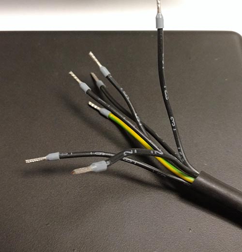
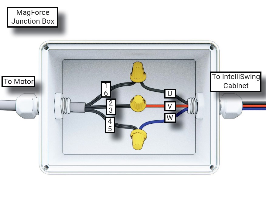
Three wires are required for each bell's motor to the MagForce control box. A cable (18 inch long) is permanently attached to the motor with seven wires (1-6 and ground). They are connected in the bell motor junction box as follows:
U output to motor leads 1 and 6
V output to motor leads 3 and 2
W output to motor leads 5 and 4
Single phase MagForce panel
The MagForce control panel for single phase will have a capacitor on the output between outputs U and V. If the motor is sized to require an overload protector, the L1 connection to the triac input will be routed in a serpentine fashion through the three overload circuits. This is required to prevent trips caused by the missing phase detection.
Programming Procedure (PERIOD proximity)
IMPORTANT:
- If a rotary encoder is installed on the headstock spindles (chip on control board has a label marked SENSOR)
- Then go to the rotary sensor programming procedure and use the parameter options there for MagForce Linear motors.
- If the bell with a proximity sensor is being serviced (chip on control board has a label marked PERIOD)
- Then continue to use this programming procedure
Using the Terminal
The right cursor button will take you through the settings for each bell in the system. From the status window, shown below, you can cursor left to select another bell. To change settings you can increment/decrement using the up and down arrow buttons, or input the value with the numeric buttons and save it with the EXE button.
The two line programming status screen should look like this (first and fourth lines are our labels):
    Swing Angle      Motor Pulse Time      Tempo
         20.0               24           #101.
         84                *14           Start
     Motor RPM    (*Sensor) Ideal Pulse    Status
When the bell is swinging, the display will indicate the current Swing Angle to the nearest tenth of a degree, the Motor Pulse time in milliseconds, the Tempo in beats per minute, the motor RPM (for rotary) and the asterisk will blink when feedback from the sensor occurs. The Ideal Pulse is the time in milliseconds that will maintain the desired swinging angle. Status will be Start, Stop, Restart, StartP, Calc-P or Calc-Imp, indicating the swinging/calculation mode.
Initialize
To reset all settings to default, go left to the Language selection screen and press the DEL button.
Calibrate Swing Timing
For proximity (period) sensor systems, set the transmission value to 5.0. In order to calibrate the angle of the bell to the swinging period, set the Oscillation value as follows:
- Go to the 1Oscillation screen. The default value at the top of the display is 900. The bottom of the display should read "Stop" and "180" (if not set yet)
- Press the ON button - the display will say Measure.
- Have someone move the bell by hand so that the proximity sensor begins to blink. At this point the number beside "Stop" should begin to change and there should be a blinking asterisk to the right of "Stop."
- If this does not happen, check the sensor connections. If the light on the sensor is on when the flag is near it, and off when the flag moves away, the sensor has power (through the + and - wires), but the output signal is not getting to the D input on the control board.
- Swing the bell by hand (or by use the EXE key to electrically pulse the motor if you can not reach the bell) to a little more than 20 degrees. The bottom number will begin to change first, indicating what the controller estimates the maximum angle of the bell to be based on the fixed period on the top line.
- After five consecutively similar swings, the swing period at the top of the screen should change from the default value of 900 to the actual swinging period of the bell (in milliseconds).
- After the bell has coasted to about 20 degrees, watch for the period to update then press the ON key to save it current period. The display will say Stop and the top period will remain static. The bottom right number will indicate the approximated angle that the bell is swinging.
- this measurement is not extremely critical, but inaccuracies in the period will impact the following:
- The angle that you select below will not be the true angle, but if you can get the bell to ring properly, don't be overly concerned with the number.
- If you set the Oscillation period too high, the start period will be too long and the bell may fight against the period at start up. It is better to set the oscillation period to an angle that the motor can reasonably reach with the start pulses than an accurate 20 degrees.
- You can manually swing the bell and the system will display its estimated angle on the bottom line. If you can manually make the bell ring satisfactory by hand, note this displayed angle and put it in the desired angle setting. Only keep this arrangement if the motor is able to start from a standstill with these settings.
Select Swing Angle and other parameters
Set the Swing Angle to 25 to 30 degrees - a starting point for experimentation. If you know the 1Oscillation to be set to less than 20 degrees then start testing with an Angle of 40 to 50.
Set %Start to 50. The default is 95. For proximity sensor systems, this value determines the percentage of the startup period (set in 1Oscillation) the motor will be energized until the sensor provides a period signal. Too long of a pulse will end up braking the bell as it stalls and swings back on the first pull. If the bell has a hard time starting, experiment with different values here, and also the number of starting pulses (see below). Errors will result if the sensor doesn’t see a change before the number of start pulses has counted out.
Set %Brake to zero while in the setup mode to prevent overheating while testing.
Set StaImp to 8 or 10. During testing below, count how many pulses it takes for the proximity sensor to see the flag go away, then you can set this to about 2 over that count. The maximum value is 20. If you are using more than ten, experiment with other values of %Start to get the bell moving with fewer pulses.
Set MaxAmpli to a large value like 90 to 120 (unless there are obstacles the bell might collide with) it will default to ten degrees higher than Angle before auto calculations then 5 degrees higher when testing is complete. A higher value will prevent shutdowns for exceeding the maximum angle during experimentation (error status = MaxAmpli).
P-regulator and I-regulator both default to 50 for fully automatic calculations. Semi automatic calculations are made when they are set to equal values other than 50; in that case only the ideal I will be calculated and saved (no restart needed, P will be stored with the value you set). If the bell is easy to swing a quicker semi-automatic calculation will result with both P-regulator and I-regulator both set to 25. Try the default of 50 first, then change to 25 (with a strong motor) if the CalcImp mode seems to ‘hunt' for a long time. If the motor is suspected to be weak for the bell, set both regulators to a higher value such as 75.
The automatic calculations should be finished within ten minutes. If it is taking longer and you are happy with the way the bell is ringing, you can terminate the calculations using the current settings. To do this, keep the bell swinging and set I-regulator to zero. The display will change to 'Swing' and you can stop the bell. Make sure it starts correctly with the saved values after coming to a complete stop.
Automatic calculation
Overview
Before you begin, make sure that the motor overload is on so current can get to the motor. Overloads have two buttons on them, a black Start and red Stop button. The black button should be pressed.
The bell needs to swing two times (full automatic setting) so the controller can experiment with the required pulses. These parameters will only be saved after the bell has been rung twice.
The first time it will say Start then Calc-Imp then Swing. At that point you can stop the motor by pressing ON the status display will read Restart, but wait until the bell has come to rest before starting the next experiment.
The second time, the display status will say Start then Calc-P then Swing. The calculated parameters are not saved until the status display reads Swing. After you stop the motor the status display will read Stop. The calculated parameters are saved in non-volatile memory. You can verify this by checking that the I-regulator value is zero. Power can be safely turned off at this point.
First Swing Experiment
Calculating the ideal impulse
Press ON to start the first automated experiment. Status on the lower right of the display will read StartP until the system has fired the number of impulses you specified in StaImp, or the flag exits the sensor. Next it will read Start as it approaches the desired angle. When it begins to search for the ideal pulse, it will read CalcImp.
Potential issues
- If the bell isn't swinging high enough to ring, but the controller stops sending impulses to the motor during CalcImp, then increase Angle.
- If the bell swings too high on the first pulse, reduce power in the %Start and/or PowerStaSwi parameters.
- If the bell seems to be fighting itself to get started, experiment with smaller values of %Start (length of start pulse).
- If you get Err MaxAmpli then there is some reason the bell isn't coming back to the home position in a reasonable amount of time. Check for friction in the bell pivot bearings or a lack of rigidity in the reactor plate so that it doesn't get pulled into the motor and cause mechanical braking action.
- If you get ErrBlo (blocked bell):
- It may need more starting pulses to exit the sensor. Try increasing StaImp (number of allowed blind pulses).
- Check that you properly set the 1Oscillation above. If it is still 900, you did not complete the procedure. Do it again.
Success
When Swing appears on the display, the system has calculated the ideal impulse (middle value on the lower line on the status screen) to swing the bell. If you would like the bell to swing higher or lower, try other values for Angle and MaxAmpli. It will recalculate the ideal impulse based on changes you make at this time.
When you like the angle and the display again says Swing you can press ON to stop the bell swinging. Wait for the bell to come to a full stop.
The terminal display will indicate Restart to indicate that the second experiment is required.
Second Swing Experiment
Calculate the over/under Proportional correction factor
The system will not require a second swing if you set P-regulator to values other than 50. It will use your parameter and expect you to verify that your value will work properly.
Press ON to start the second experiment. The terminal display will say CalculP while it is determining the setting for the P-regulator. This is the amount that will be subtracted from the ideal motor pulse when the bell swings too high. It is also added to the ideal motor pulse if the motor swings too low.
When Swing appears on the display, the calculation is complete and you may press ON to stop the bell. Wait for the bell to come to a full stop.
In some cases, the display may say Restart instead of Stop because the motor may not be ideally sized for the bell and values for P and I could not be found in the normal range (generally near 50). If this occurs, tweak the PowerStaSwi (and maybe P/I-regulator if that doesn't help, see above) parameter and press ON again until you see Swing. You have not successfully finished the setup and the parameters are not permanently saved until you reach status=Swing.
Interpreting the results
Calculated values of P-regulator will provide you with information regarding the ease that system has ringing the bell. Low values of P-regulator (< 25) indicate that the motor easily swings the bell. You can reduce PowerStaSwi which is the soft start current limit parameter to pulse the motor more gently.
Additional Tests
Testing performance and re-calucuating after making adjustments
Further experiments (first and second swing) must be re-run if you adjust Angle, PowerStaSwi, Pos-Impuls or Transmiss after calculations are complete.
The ideal impulse is not written to memory unless I-regulator is zero. It will automatically go to zero when the system has finished calculating the value. If you entered your own value for P-regulator then you will also have to set I-regulator to zero yourself to save it in memory (manual setup mode), then swing the bell again to make sure it works. Adjustments to %Start, %Brake, PowerBrake1 and PowerBrake2 can be made at this time without having to recalculate Ideal pulses. You can test them to be sure the motor overloads do not disengage when this happens.
Do not use braking with retrograde (counterbalanced) clappers. Bell damage from a severe impact may occur if the clapper gets out of phase with the bell and they collide from opposite directions.
Adjust Assym as needed so that the clapper rings evenly on both sides of the bell.
Stationary Overload Test
After everything else is completed, you can adjust the motor overload (if installed on 1HP and larger motors) current setting to trip within 40 seconds of a locked rotor condition. Click the left arrow (5 clicks) from the Status screen until you get to the Test-PKZ page. Press the ON button to turn on all phases in such a fashion that the motor does not run (simulation of a locked rotor). Then adjust the overload so that it trips before the on-screen timer reaches 40 seconds.
Note that on single phase systems, the load must be routed through all three circuits of the overload. The W motor lead must be wrapped around and run through each overload circuit in series so all three internal overload heaters have the same temperature. Overloads are designed to detect missing phases this way and will trip quickly if any are detected to be missing.
Final Settings
Make a record of the following settings for future reference when setup is complete:
- Bell Number
- 1 is the largest bell
- Dimensions
- Air gap between motor and reactor plate (typically 1/4 to 3/8 inch)
- Center of bearing spindle to center of motor
- Swing Angle
- Intended swinging amplitude angle in degrees
- Transmission
- Rotary code wheel to angle ratio
- always set to 5.0 for proximity sensors
- %Start
- Percentage of swing angle for starting pulses
- %Brake
- Percentage of swing angle for braking pulses
- 0 = No braking, 100 = brake until stopped
- 1Oscillation
- Period in milliseconds for one complete swing cycle at 20 degrees of amplitude for proximity sensor calibration
- Reset value is 900, may be less for very small bells, usually higher for most bells
- Pos Option - not used
- PowerStaSwi
- Power reduction using soft-start current limiting 1-8
- 9=full inrush current which may trip circuit breaker
- Power Brake 1
- First brake at amplitudes > 20 degrees current limit 1-8
- Power Brake 2
- Secondary braking at amplitudes < 20 degrees current limit 1-8
- StartImp
- Maximum number of impulses allowed before home sensor begins to provide motion feedback
- If no feedback is received after this number of tries, the system will go into safety shutdown
- XtrBrakeImp
- Extra brake impulses after home sensor no longer provides motion feedback
- Should be 0 as blind braking is not advised
- MaxAmpl
- Maximum swinging angle before safety shutdown
- Set to 90 if no obstacles are in the way of the bell swinging high
- P-Regulator
- Proportional regulation factor for correcting motor pulse
- I-Regulator
- Ideal pulse width to maintain selected angle
- This is zero on the terminal when parameters have been successfully calculated and saved
- Pos-Impulse
- Position of the motor impulse in the sweep of the bell
- 0 = home, 100 = turnaround
- Always set to 0 for MagForce
- Assymmetric
- Proportion of motor pulse for forward/backward balance
- 50 = equal pulses, 100 or 0 = unidirectional drive forward or back
After setup complete
Disconnect the programming terminal. The front panel switches and the Chime Master relays will not activate the motors while the programming terminal is connected.
