Bell Control Technical Data 3700
Libertas 3700 series modular relay and high current switching panels provide consistent ringing with accurate pulse timing.
Technical description
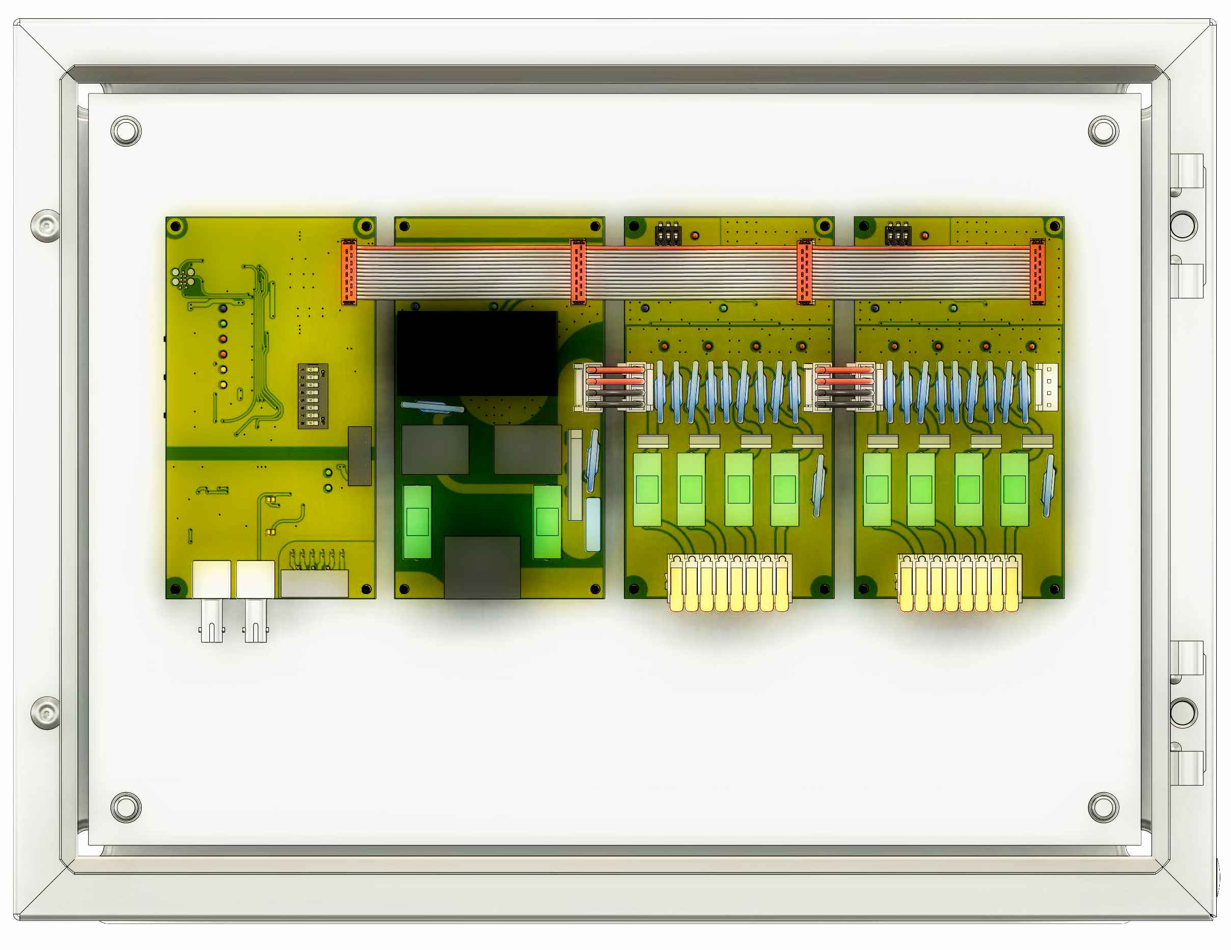
From left to right, each panel includes the following modules
- Interface Module
- Power Supply Module
- Output Module(s)
- DC Striker T4 - four DC striker outputs
- Combination Output - one DC striker and three motor control dry contact relays
- Relay Module M4 - four dry contact relays, typically used for motor control
Module Connections and Warnings
The modules are tied together using a ribbon cable that carries low current power, control voltages and logic signals. Additionally high voltage DC jumpers feed 200VDC from the Power Supply Module to the DC striker output modules.
CAUTION - HIGH VOLTAGE
There are no user or field serviceable parts on the modules. Send suspect or faulty modules to Chime Master for repair or replacement.
The low current ribbon cable at the top of the modules carries 12VDC and lower local potentials for logic signaling, but when a DC Striker module is part of the panel, the ribbon cable will have LETHAL VOLTAGES from the ribbon cable to EARTH GROUND when the Blue ACTIVE lights are on.
Do not attempt to troubleshoot or reprogram logic when DC Strikers or Combination Modules are connected to the power supply DC HI VOLTS header J2. The logic low current ground is not isolated and is referenced to -200 VDC.
SAFE CONFIGURATION
The interface module features both a galvanically isolated, twisted pair wired interface to the control panel and an optional optical interface. Interface Module connectors located at the lower portion are safe.
When the modules are secured to the relay panel, and cables are installed, high voltage present on the bottom of the modules is not touchable. The test button housings are grounded to the electric panel, which is bonded to Equipment Earth ground attached to the power supply module.
Interface Configuration Switch
- Panel Address
- Non-musical bell controls: 1, 2, 3 - OFF
- First panel for Carillons: 2, 3 - OFF; 1 - ON
- Second panel for Carillons: 1, 3 - OFF, 2 - ON
- Third panel for Carillons: 2, 3 - OFF; 3 - ON
- Map Select
- Non-musical bell controls: 5, 6 - OFF; 4 ON
- Chimes with missing semitones: 4, 6 - OFF; 5 ON
- Carillons: 4, 5 - OFF; 6 ON
- Custom: 4, 5 - ON; 6 - OFF (sticker on Interface Module has an Fnnnn number)
- AX Mode: 7 - not implemented yet
- High Baud
- Non-musical bell controls: 8 - OFF
- Chime and Carillons: 8 - ON
Module Address Switch
Module addresses are human readable (not binary). The switches are numbered 1 to 3 left to right at the top of each module. Set module 4 as 3+1, module 5 as 3+2.
For single panels needing 25 to 32 note outputs, module number 7 (switches 1+2 ON) and 8 (all switches ON) will be specified, but these addresses are generally reserved for Combo modules.
Non-musical controls
Combo Modules do not have address switches. If two are used, the second one will have its address jumper soldered.
Quad output modules are set as follows:
- First striker module 0 - All switches OFF
- Second striker module 1 - Switch 1 ON
- First motor relay module 2 - Switch 2 ON
- Second motor relay module 3 - Switch 3 ON
Chimes
Single panel of up to four modules numbered left to right.
- Interface configuration Map switch 5 is ON.
Modules addressed from 0 up to 3
- Up to 13 diatonic notes plus the leading tone, sharp 4th and flat 7th semitones
Modules addressed from 1 up to 4
- Up to 15 diatonic notes plus the flat 7th semitone
If other semitones are needed, use a carillon configuration skipping outputs as not needed.
Carillon panels
Carillon panels come in three sizes. Notes given are for a non-transposed instrument. Transposition is set up in the controller if needed.
- Interface configuration Map switch 6 is ON.
Five output modules
Up to three 20 output panels support five octaves minus one semitone. Address the modules from 1 to 5:
- Panel 1 skips first semitone for notes C to G#
- Panel 2 outputs notes A to E
- Panel 3 outputs notes F to C
Six output modules
Three 24 output panels support six octaves fully chromatic. Address the modules from 0 to 5:
- Panel 1 outputs notes C to B (first two octaves)
- Panel 2 outputs notes C to B (third and fourth octaves)
- Panel 3 outputs notes C to B (fifth and sixth octaves)
Custom mapping available for sub-bourdons and missing semitones.
Seven or eight output modules
From 25 to 32 fully chromatic outputs on a single panel. Address the modules from 0 to 7:
- Module 6: 1 and 2 ON
- Module 7: 1, 2 and 3 ON
Installation
Primary power from the local disconnect is connected to the Power Supply Module at L1 and L2. Earth safety is tied to the third terminal with the ground symbol (bonded to the chassis).
Strip input and output wires to 3/8 inch (10mm) for lever action terminals. Take care to insert all strands of wire into the terminal and that they do not contact each other outside the terminal.
Interface to controller
AX Systems with data cable
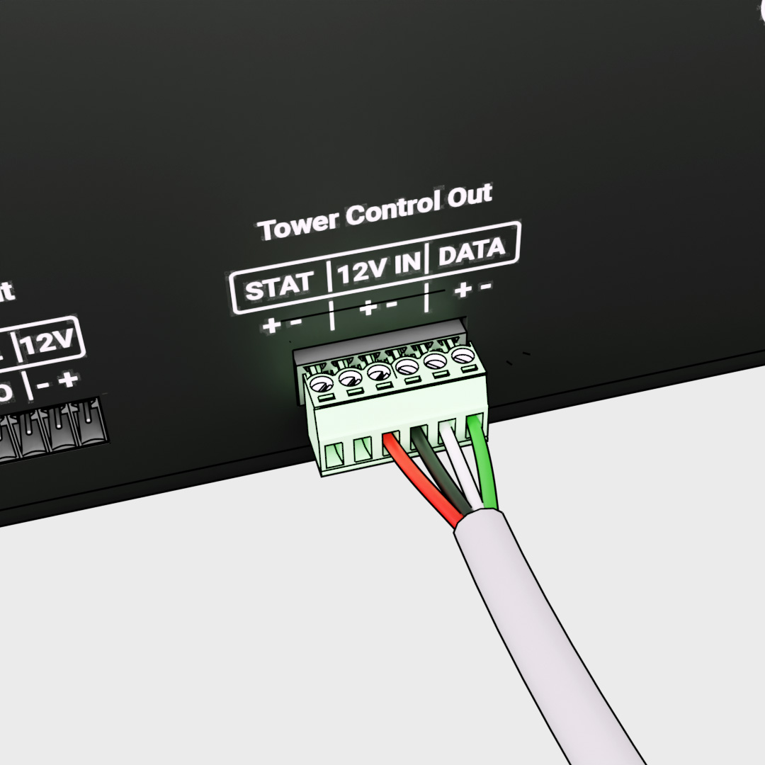
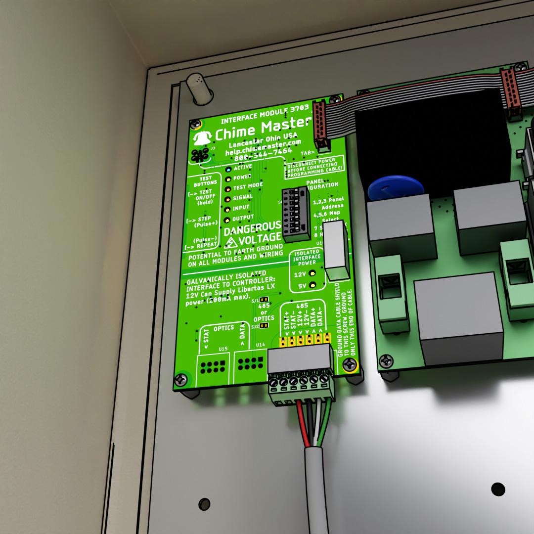
The 485 input connector is pinned out one to one the same as the AX tower connector. When multiple panels are used, parallel the data cable to all panels.
Four wires (two twisted pairs) are enough unless AX STATUS mode is used (not implemented at the time of this writing).
- STAT+ (not used)
- STAT-
- 12V+ (used to power the isolated inteface in the controller)
- 12V- (isolated data common and interface power - NOT Earth or cable shield)
- DATA+ (control data from the controller)
- DATA-
If shielded cable is used (recommended), connect the shield to the lower right mounting screw of the Interface Module. Do not connect the shield at the controller end.
AX Fiber optic cable
Use Multi-mode Duplex cable with two ST connectors at each end. Use care when installing the cable to prevent kinks and damage to the ends. The ends should be marked by color, number or with specification text on one channel of the 'zip' cord. Whichever channel is plugged into the left STATUS of the tower panel, also connects to the left STATUS connector on the rear of the AX touch screen controller. The opposite color should be plugged into the right DATA connectors at both ends.
For multipanel carillon installations, only Panel 1 will have the optical interface. Parallel the 485 terminals of Panel 1 and the additional panel(s).
LX Systems
Sufficient power is available from the 12V terminals of the interface to operate the LX control panel. If the data cable length causes the supply voltage to drop so that the LX control panel does not operate, try the following remedies.
- Use additional spare wires in the data cable to carry more current.
- Plug a booster power suppply into the 12VDC input of the control panel.
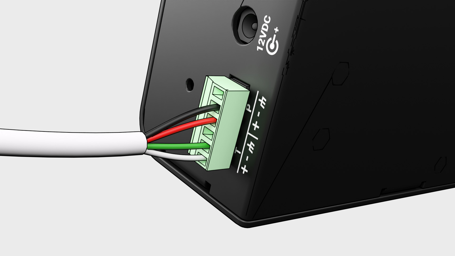
- STAT+ (not used)
- STAT- (not used)
- 12V+ (connect to P+ terminal 4 on LX controller)
- 12V- (connect to P- terminal 5 on LX controller)
- DATA+ (connect to T+ terminal 1 on LX controller)
- DATA- (connect to T- terminal 2 on LX controller)
Chassis ground for the LX controller pins 3 and 6 can be obtained using the bottom right mounting screw of the relay panel's interface module.
DC Striker outputs
3721 Combo Module
One DC striker output is provided on the Combo Module. Connect one 200 VDC striker or hammer to the POS and NEG terminals. Polarity does not matter.
3731 Quad DC Striker Module
Four DC striker outputs are provided on each of these modules. Typically the bells are connected to the outputs from left to right in order of size, large to small.
For five striker outputs, a combo module may be installed to the right of the quad module. The bell that connects to the Combo module is the largest bell. The smaller bells will be connected left to right in order of size to the quad module.
Polarity + (POS, Positive) and - (NEG, Negative) refers to the power supply connection. Strikers and hammers do not care about their polarity connection. In some cases (for smaller bells) a common positive line may be run to the tower from a POS output terminal for up to four strikers.
Typically a pair of wires from the striker will connect to two terminals:
- POS terminals are all bussed together on the module
- OUT1 .. OUT4 use advanced transistors to pulse the Negative 200VDC supply to the strikers
Double check stranded wiring to be sure the output terminals do not have stray wire strands that might short the outputs. The output fuses rarely protect the transistors from shorted outputs.
Swinging motor outputs
3721 Combo Module
This module supports up to three swinging bells.
Connect low current swinging motor enable lines to the 3740 Relay modules as follows:
- intelliSwing motor panel L1 OUT (from logic circuit breaker) connects to 3721 FUSED INPUT terminal
- intelliSwing motor panel S1 IN (switch input) connects to 3740 1 N.O. terminal
- subsequent motors similarly connect to their respective outputs.
3740 Quad Relays
This module has four normally open dry contacts with a common input.
Connect low current swinging motor enable lines to the 3740 Relay modules as follows:
- intelliSwing motor panel L1 OUT (from logic circuit breaker) connects to 3740 INPUT terminal
- intelliSwing motor panel S1 IN (switch input) connects to 3740 OUT1 terminal
- subsequent motors similarly connect to their respective outputs
- the dual 3740 INPUT terminals may be used to daisy chain modules for more than four outputs
Other output options
High current solid state relays may be used to switch AC or DC loads as may be required for special applications. These connections will be made to terminals provided according hookup diagrams supplied with the panel.
Troubleshooting
Lights in normal operation
Interface module
- ACTIVE: indicates the high voltage relays are enabled. Indicated from logic before drive transistor.
- Active only on when outputs are active. Resets at end of concert.
- POWER: 12VDC Power supply from Power Supply Module is on and 5V regulator is OK.
- Should be as bright as power light on Power module.
- TEST MODE: indicates self test is active. Inputs are ignored.
- SIGNAL: blinks with input data.
- Should never be constantly lit except dim glow in Bit Map mode.
- Blinks brighter when receiving low Baud signal.
- INPUT: indicates that input data addressed to this panel, or
- Steady Blink if configuration switch error.
- Will not blink if incoming activation data is for this panel, but no module has been installed for it.
- OUTPUT: indicates that this panel is sending status back to the controller.
- Blinks brighter when set for low Baud.
- 12V: DC-DC isolation converter is working - 12V available on 485 interface terminal
- Should be as bright as power light on Power module.
- 5V: interface regulator is working (may be damaged by surges induced to data cable)
- Should be as bright as power light on Power module.
Power module
- Power - 12VDC Power supply is working and AC input is within 100-240VAC
- Active - indicates the high voltage relays are enabled. Indicates Interface Module drive transistor is OK.
Output modules
- Ready - indicates that interface module has enabled the outputs (not in sleep or reset mode).
- Active - indicates the high voltage relays are enabled. Indicates signal over cable is OK.
- ERR - indicates improper signal received for module (if input not blinking on Interface module).
Error lights
Configuration error
Configuration errors are indicated by blinking Input light on the interface board. If no error lights are lit on output modules then the problem is an invalid setting of the Panel Configuration switch on the interface board. If an error light is lit on an output module, its address switch is incorrectly set for that type of panel.
Correctly configured modules will result in a self test that activates outputs from left to right (in Up sequencing mode).
- Two modules error lights do not come on (other modules do)
- Modules at the same address must be the same module type - the modules with Err lights off are the problem
- Modules have error lights regardless of switch setting
- Check that the ribbon cable connection on all modules is fully seated
Operational error
If error lights occur on output modules, the following operational errors may be indicated:
- All module's error light comes on and stays on.
- If Bit Map mode is selected, a constant input data stream is needed. Check connections between the panel and controller. The interface module's Signal light sould be indicating presence of the input signal. Perhaps the controller has not been configured for Bit Map mode.
- One module error light comes on. The error resets when the Active state comes on next time.
- This indicates that the output pulse exceeded the modules maximum pulse time. Reduce the pulse time on the controller (AX or Bit Map modes).
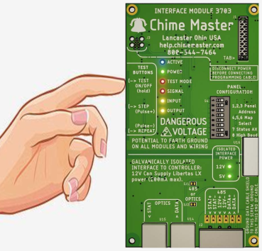
Test buttons
Self test will time out to normal operation in three minutes (from last output test) unless it is left in the repeat or scan modes. Those modes will operate continuously until canceled.
- Quick Tests
- Long Press Test- enters test mode from normal mode - exits test mode
- Double Click Test - test reset to output 1 up direction
- doesn't fire output
- discards all output timing edits
- Click Test - cancel repeat/scan modes, reverse output step direction
- Click Step - cancel repeat/scan, go to next available output and fire
- Click Repeat - cancel repeat/scan, fire current output again
- Leave panel in test mode for burn in or bell adjusting (CAUTION! No Time Out)
- Double Click Step - fire next, continue scan all outputs until cancel w/single click
- Double Click Repeat - continue to fire current output - repeat until cancel w/single click
Adjust output pulse time
Does not affect motor enable outputs to intelliSwing panels, but will affect Relay modules if used to trigger striker outputs.
Available striker pulse times (milliseconds - setting is indicated by blinking Input LED):
- 75 - one blink - only for very small bells in chimes and carillons for faster repeat
- 100 - two blinks - (Carillon panel 3 default)
- 150 - three blinks - (Carillon panel 2 default)
- 200 - four blinks - Default (most panels)
- 300 - five blinks - Deagan 'O' type striker
Only use the following for Deagan or motorized strikers
- 550 - six blinks - Deagan 'G' or 'L' type stiker
- 600 - seven blinks - Deagan 'F' type striker
- 650 - eight blinks
Click the Step button to get to desired bell output, then long press Step or Repeat until Input LED indicates new pulse width.
- Long Press Step - (up) lengthen output pulse
- Long Press Repeat - (down) shorten pulse
- Click Repeat - re-test using new pulse
- Long Press Test - saves newly selected timing for all bells before exiting self test
- During save, Input LED blinks four times
- Double click Test - revert to last saved pulse times (losing any recent changes)
If you want to reset to default pulse times to factory defaults:
- Change the module configuration as follows
- Power off the panel
- Unplug ribbon bus from one of the modules
- Power on, wait for two seconds and power back off
- Plug the ribbon bus back into the module
- Power on the panel
Other applications
Minute impulse clocks
This application requires a 3721 combo module with dry contacts to switch the voltage to the minute impulse clock movements.
- set all three Panel address switches ON
- set map switch 4 ON
- set high baud ON if system plays music (speakers or bell clappers)
- output 2 N.O. is odd minutes
- output 3 N.O. is even minutes
- a single DC tolling hammer output is provided to ring the hour
Deagan Damper relay
This relay panel supports up to 32 Damper outputs to be used in conjunction with a striker panel for single tone or harmonic Deagan Tower Chimes. We have improved upon Deagan's model 72-74 mechanical relays in conjunction with our Libertas AX controller.
- Harmonic bells supported with a sustain pedal that works like a piano during chord changes
- Single tone (melody only) playing never requires sustain pedaling or legato keying
- Adjustable transition time to delay note muting
This application requires DAMPER firmware installed on the interface module.
- set the Panel Configuration switches the same as the striker output panel
Refer to the pulse setting instructions above to adjust the transition time between notes while in the self test mode. This is a single setting for all notes in the chime (unlike striker pulse timing). Exiting self test mode will save the adjustment permanently to non-volatile memory.
When new notes are played, the transition time allows the previous note to ring longer before its Damper is released to mute the note. This time is adjustable in eight steps from none (immediate mute) to one second.
Repairs
Do not unplug cables or make wiring changes while module power lights are on. Turn off circuit breakers or disconnects first.
When replacing a module with a configuration or address switch. Make sure that the switch on the replacement module matches that of the original module before powering the panel.
DC Striker Module
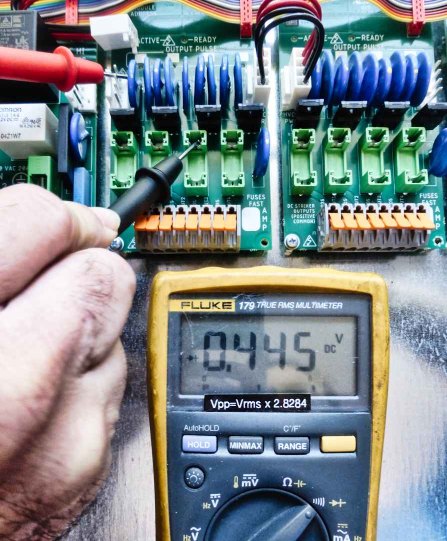
You can use a digital multimeter to check the IGBT output drivers of the DC Striker Module.
- Make sure the panel is powered off (circuit breaker or local disconnect)
- Unplug the power cable from the Power Supply Module that feeds high voltage to the DC Striker Modules
- Remove the output fuses from the module
- Set the multimeter to Diode Junction test mode
- Hold the red meter probe to the top power pin
- Check the top contact of each fuse holder on the module
- The voltage drop should be around 0.5 Volts - shorted outputs will be near 0 Volts (and fuse will be blown - do not replace)
- Return the module to Chime Master for replacement/rework if any measurement is less than 0.35 Volts
Combo Module
To test the striker output of the Combo module, use the steps above as for the DC Striker Module.
- Hold the red meter probe to the bottom of the striker fuse
- Touch the black meter probe to the middle lead of Q1
- The voltage drop should be around 0.5 Volts - shorted outputs will be near 0 Volts (and fuse will be blown - do not replace)
