No sound
This page is for electronic carillon troubleshooting when no sound is heard outside.
Preliminary checks
You can generally get a system to play music for testing by pressing button 4 then the green Enter button.
- Determine if the inside speakers work.
- Newer systems have monitor speakers and level controls on the carillon module. This will not check connections or devices other than the carillon unit itself.
- Older systems have monitor speakers and level controls on the amplifier module. Sound from the inside speaker generally indicates that the amplifier is operating correctly and connections between the amplifier and carillon modules are good. Make sure the Tower switch is turned on if there is one.
- Double check all connections
- Amplifier power cord
- Audio cable between the amplifier and carillon modules
- Outside speaker cable to amplifier output terminals
Testing amplifier
- Be sure that the amplifier is getting turned on completely by the system.
- Unplug the amplifier's power cord from the switched outlet on the rear of the carillon module and plug it directly into a live wall outlet and re-test.
- Check the amplifier passes input signals to the output
- Unplug the amplifier's input signal cable from the output jack of the carillon module. While the amplifier is powered on, tap the tip of the plug on the end of the cable and listen carefully to inside and outside speakers for a buzzing sound when your finger is on the tip of the plug (helpers with good hearing may be needed).
- Disconnect the outside speaker cable and temporarily connect a spare speaker to the amplifier output. Recheck using both the carillon outputs and/or tapping the input cable again.
Testing Speakers
First, it is crucial to determine which model of audio drivers are being tested. See sections below for information on each model.
Once the driver model is determined, disconnect the outside speakers from the two terminals on the back of the amplifier.
Put a DC ohm meter across the leads going to the tower.
If the reading is higher than the listed value, then one or more of the drivers could be open, or a connection is corroded.
If lower, one or more drivers or the wiring may be shorted.
Determine the resistance of the Ohm meter's own leads by touching the two test leads together. Subtract the displayed value from measurements before comparing to those given below.
SJTO-14 wire supplied by chime master will add about 0.0056 ohms per foot to the driver reading.
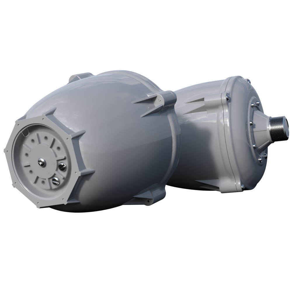
PD60A Drivers
- Single functional PD60 driver will read approximately 9.5 - 10 ohms directly from the terminals on the driver, not including any wire
- Four PD60 drivers will read approximately 2.5 ohms when wired together in parallel with a short length of wire
- Two PD60 drivers together will read approx. 5 ohms when wired together in parallel with a short length of wire
- Four PD60 drivers wired into a speaker line roughly 250ft. in length will read approx. 3.8 ohms
- Four PD60 drivers wired into a speaker line that is 25ft. will read approx. 2.7 ohms
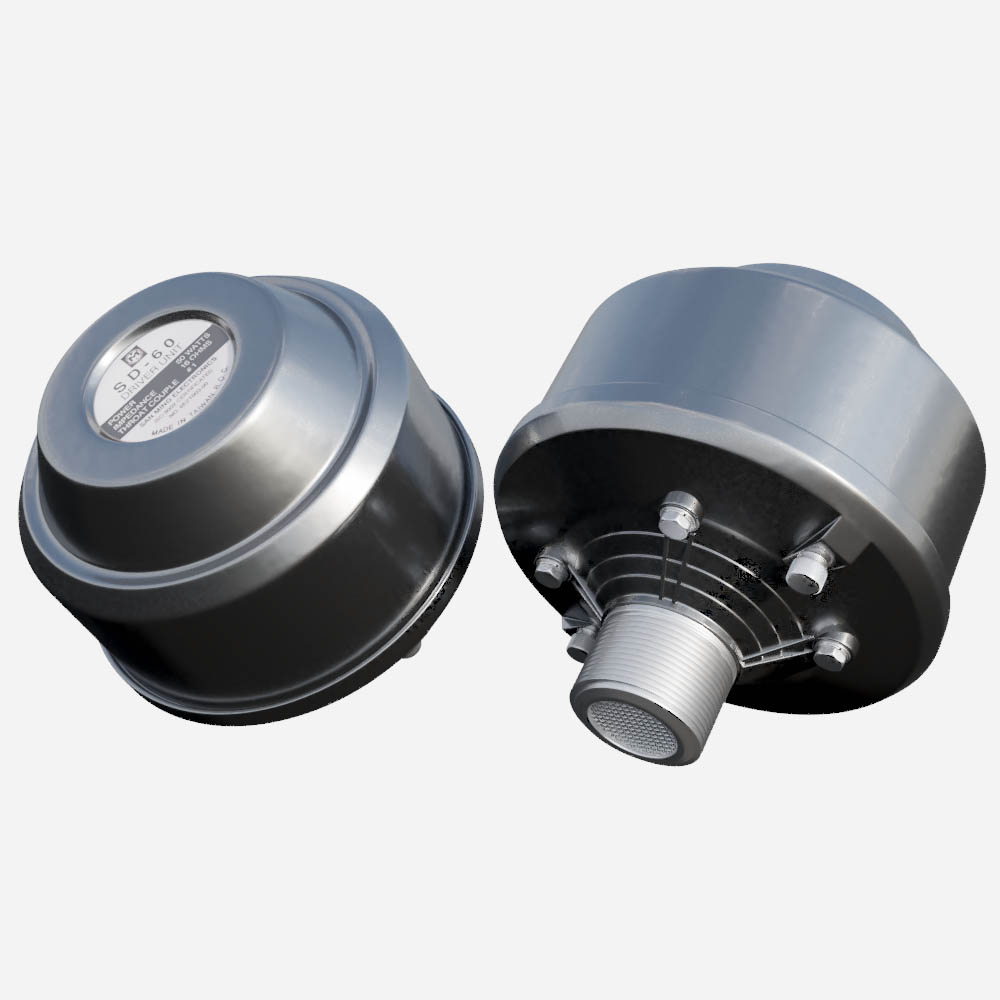
SD60 drivers
- Single functional SD60 driver will read 9.5 - 10 ohms directly from the terminals on the driver, not including any wire
- Four SD60 drivers will read 2.5 Ohms when wired together in parallel with a short length of wire
- Two SD60 drivers together will read 5 Ohms when wired together in parallel with a short length of wire
- Four SD60 drivers wired into a speaker line roughly 250ft. in length will read 1.4 Ohms
- Four SD60 drivers wired into a speaker line that is 25ft. will read 2.14 Ohms
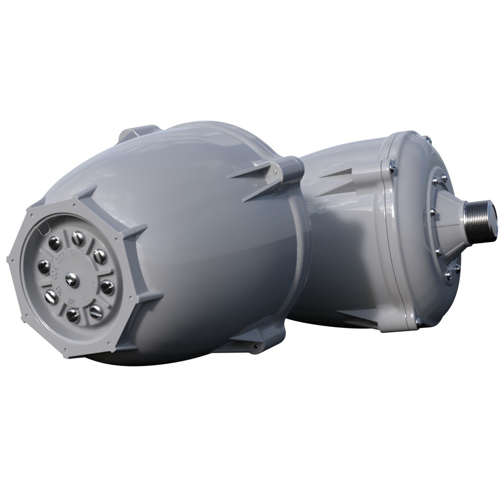
PD60AT Transformer Drivers
These drivers have several possible taps they could be hooked up to. Our examples show a typical 60W tap connection. Even the 16 ohm tap is a transformer winding, so the condition of these voice coils can not be determined without disassembly. Four large screws will remove the back shell (where the transformer is mounted) from the diaphragm assembly. The red and white voice coil wires can be disconnected from the transformer and measured directly. A good voice coil should read 9-10 Ohms DC.
The following measurements may be useful to determine initial condition of the speaker line.
- Single PD60AT between Common and 60W tap = 2.8 Ohms (regardless of voice coil condition)
- Two PD60AT drivers measured through 250 feet of speaker line = 2.8 Ohms
- Four PD60AT drivers measured through 250 feet of speaker line = 2.1 Ohms
- Four PD60AT drivers measured through 25 feet of speaker line = 0.9 Ohms
Testing speaker line
- At the amplifier location, disconnect both wires of the speaker cable from the amplifier. Take preliminary measurement with speakers still connected on the two wires of the line at the amplifier end. Compare to the readings above (Testing Speakers) and write it down.
- Leave the two wires at the amplifier end disconnected, not touching each other, or any other conductive material.
- Go to the speaker location, open the junction box, disconnect the cable from the amplifier from the speakers and take a measurement. There should be no resistance reading (no change on the Ohm Meter's display). Any numerical reading on the meter will indicate a short on the speaker cable.
- At the speaker location, short the two wires together on the cable that runs down to the amplifier. Then at the amplifier end of the cable put the Ohm Meter test leads on the two wires of the cable. A non-numeric reading will indicate an open (possibly cut) cable. For 14 AWG SJTO cable and a low voltage DC Ohm meter, you should see about 0.006 Ohms per foot of cable (don't forget to subtract the resistance of your meter's leads).


