|
|
| (15 intermediate revisions by the same user not shown) |
| Line 1: |
Line 1: |
| <div style="font-size:84%">'''[http://www.ChimeMaster.com Home] > [[Chime_Master_Help|Help]] > [[Installation_documentation|Installation]] '''</div><br /> | | <div style="font-size:84%">'''[http://www.ChimeMaster.com Home] > [[Chime_Master_Help|Help]] > [[:Category:Installation|Installation]]'''</div><br /> |
| * [[Libertas_master_clock_controller|Libertas master clock controller specification]]
| |
|
| |
|
| == Connections == | | === Equipment and locations === |
| | Generally we provide three types of equipment to install in different areas of the facility. |
|
| |
|
| === AC power input === | | ==== User controls ==== |
| All relay panels use single phase power. Clappers and hammers operate between 208 and 240 VAC. Swinging bell motor systems come in three phase and single phase versions.
| | * [[Libertas_master_clock_controller|Libertas master clock controller specification]] |
|
| |
|
| Connect a supply of at least 20A to panels with one to three bells. Add 5A per bell that could ring simultaneously (generally no more than six will ring at the same time). Input terminals L1 and L2 accept up to 10 AWG.
| | The control panel, sometimes referred to as a master clock, head unit, and may be an electronic carillon is usually located in a sacristy or office area. Many times to save long wiring runs, it may be installed in a balcony area near the tower. In all cases, no ladders should need to be used to access the control panel. |
|
| |
|
| === Hammer and clapper outputs === | | ==== Relay panels ==== |
| The striker may be a tolling hammer mounted on the opposite side of the bell from the wheel. These diagrams detail the internal hookup of the relay panel only. Consult the appropriate [[Installation_documentation#Riser_diagrams|riser diagram]] for conduit and power requirements.
| | High current switching should be as near the bells as practical. The weather resistant relay panels are, in most cases, installed in an enclosed tower chamber below the bells. Precision intelliSwing motor control panels should be within sight of swinging bells for ease of programming. |
|
| |
|
| * [[Media:2034T1220W2.pdf|Single output bell controller hookup (PDF download)]] This relay is in a plastic box and is not weather resistant.
| | To prevent moisture from accumulating in the panels, always route conduit to the bottom of the boxes. '''NEVER''' penetrate the top surface of a relay panel. |
| * [[Media:2034T3220W2.pdf|Three output bell controller hookup (PDF download)]] NEMA relay panel for three stationary bells.
| |
| * [[Media:2034T4220W2.pdf|Four output bell controller hookup (PDF download)]] NEMA relay panel for four stationary bells.
| |
|
| |
|
| === Swinging motor outputs ===
| | Specific Relay Model Technical Data: |
| Low current relays are used to enable swinging motor systems that use either solid state or electo-mechanical contactors. Multiple relays switch a Common line for multiple bell outputs. The outputs will be labeled M1, M2 (and so on from the largest to smaller bells). These relay outputs connect to
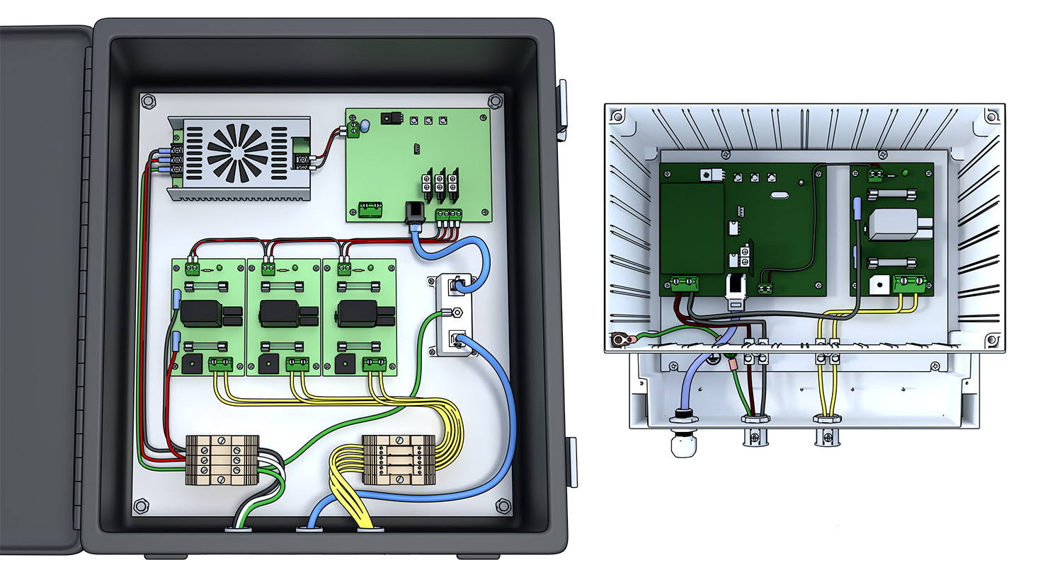
| | * ''New'' [[Bell Control Technical Data 3700|Libertas 3700 Technical Data]] |
| | [[File:3700T8.jpg|250px|link=Bell Control Technical Data 3700|Bell Control Technical Data 3700]] |
|
| |
|
| For 2052 swinging bell motors with solid state controls, connect '''M''' to each motor's '''K''' lead (a purple wire). For intelliSwing Precision systems in a separate wall mounted cabinet, connect the Mn output to the Sn switch input. For legacy motors, you need to determine which wire goes to the contactor and reversing switches.
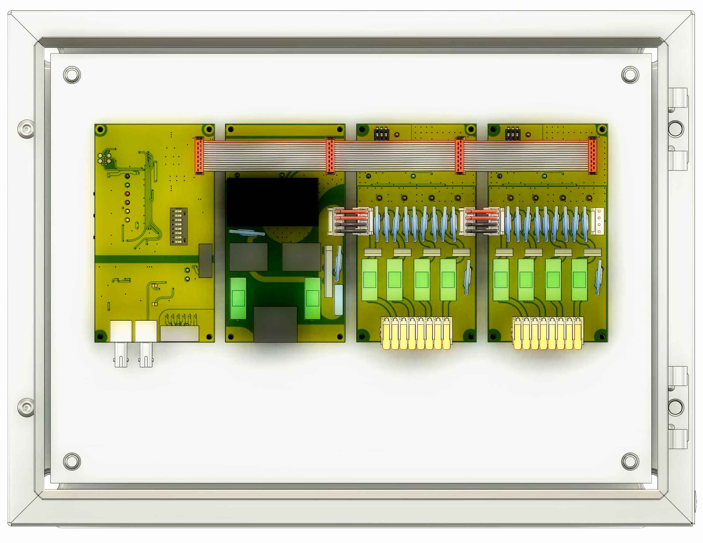
| | * [[Bell Control Technical Data 2034|Libertas 2034 Technical Data]] |
| | [[File:2034RelayPanels.jpg|250px|link=Bell Control Technical Data 2034|Libertas 2034 Technical Data]] |
|
| |
|
| Generally, connect the '''C''' Common terminal (fused at 2A) in the Libertas relay panel to L1 for most cases. If the motor doesn't run, move the jumper to L2 as power leads in existing motors may be reversed. For intelliSwing Precision motor control cabinets, there will either be a '''C''' input near the '''S''' input, or you can use the '''L1-out''' on the logic circuit breaker in the cabinet.
| | ==== Mechanical actuators ==== |
| | Tolling hammers, clappers and swinging motors are installed on the bells themselves and are usually supplied with at least an 18 inch pigtail. Junction boxes need to be located near enough to the actuator to allow connections. Flexible conduit is helpful to allow junction boxes to be re-located during the equipment installation. Separate low current conduits should be provided for swinging motor motion feedback signals (generally 12VDC logic signals). |
|
| |
|
| === Data Cable ===
| | Bells are always numbered from the largest (bell 1) to the smallest. |
| A twisted pair data cable is required and typically we use a minimum of CAT5 with RJ45 terminations. The pinout of the terminations and wire colors is the standard B style pin out. The following colors appear top to bottom when cable exits the housing to the left and the clip is away from you:
| |
| [[File:CAT5-Termination.png|400px|thumb|right|CAT5 RJ45 Termination]]
| |
| 1 Orange/White - 12VDC negative
| |
| 2 Orange solid - 12VDC negative
| |
| 3 Green/White - Data A (RS485)
| |
| 4 Blue solid - Status B (RS485)
| |
| 5 Blue/White - Status A (RS485)
| |
| 6 Green solid - Data B (RS485)
| |
| 7 Brown/White - 12VDC positive
| |
| 8 Brown solid - 12VDC positive
| |
|
| |
|
| '''Crimping Procedure'''
| | For swinging bells, the wheel side of the bell is where the swinging motor will be installed, and a tolling hammer will always be located on the opposite side from the wheel. |
| # Cut cable to length
| |
| # Strip 1-1/2" of outer jacket from cable without nicking conductors.
| |
| # Pull the jacket back from the end as much as possible.
| |
| # Fan-out conductor pairs, orange top, green, blue brown bottom.
| |
| # Untwist green, arrange green/white above blue, solid green below.
| |
| # Untwist blue, orient solid above blue/white
| |
| # Untwist orange and brown pairs, keep solids below the striped.
| |
| # Flatten the fan and bring together keeping the order shown above.
| |
| # Use scissors to cut the conductors about 3/4" from jacket.
| |
| # Double check wire order and insert conductors fully into the RJ45 connector as shown.
| |
| # Crimp the connector using an RJ45 crimping tool.
| |
| # Inspect the crimp. The wires should be fully inserted and their ends visible at the end of the connector. The gold pins should be recessed in the slots (not protruding above the plastic).
| |
|
| |
|
| == Relay panel technical information ==
| | Stationary bells can have either outside tolling hammers or inside clappers. The electro-mechanical and physics aspects of this choice generally is made on the basis of how loud the bell is intended to ring. Gravity favors outside hammers helping the power of the striking of the bell. Gravity works against inside clappers resulting in a softer tone. Visual esthetics aside, choose clappers for musical instruments and hammers for tolling bells. |
| === Wiring color codes ===
| |
| All primary wiring shall be 16 AWG or greater, stranded with 600V insulation in the following colors:
| |
| * Earth protective ground - Green
| |
| * Neutral (not generally required) - White
| |
| * L1 - Black
| |
| * L2 - Red
| |
| * L3 - Blue (when three phase power is used for motors)
| |
| * T1, T2, etc. DC striker outputs (polarity not important) - Yellow
| |
| * M1, M2, etc. Motor contactor outputs (high voltage, low current) - Violet
| |
| * COM - may be jumpered to L1 at the factory - Black
| |
|
| |
|
| Secondary low voltage control wiring shall be 18 AWG with 300V insulation in the following colors:
| |
| * Negative DC - Black
| |
| * Positive DC control - Red
| |
|
| |
| === Lights and test buttons ===
| |
| At the top of the relay panel is a square board with three buttons with four lights at the top edge.
| |
|
| |
| The four lights are labeled:
| |
| Power - Data - Fault - Status
| |
| The buttons may be labeled:
| |
| Reset - Test - Step
| |
|
| |
| At the bottom of this board, and sometimes installed on an auxiliary board attached with a ribbon cable, are one inch square output modules mounted vertically (up to four outputs on the main board, up to twelve outputs on the auxiliary board). For tolling outputs, there will be two timer adjustment controls. For motorized ringers there will not be adjustments. At the top of these boards is a green light that indicates the output is on. At the bottom of the board is a red light that indicates the output is driving a short circuit.
| |
|
| |
| === Test mode ===
| |
| Hold the Test button (under the Data light) while momentarily clicking the Reset button (under the Power light). After the Fault light blinks you can let go of the Test button. The Data light should remain lit to indicate the panel is in the self-test mode.
| |
|
| |
| Press the Step button to sequence through the outputs. The tolling outputs will ring first then any motorized outputs will follow. Note that after ringing the Motorized outputs, the toll outputs will may locked out (hammer protect mode). If you need to test the tollers again, repeat the procedure above to reset the test mode (after the bells have ceased to swing).
| |
|
| |
| To repeat an output that you have stepped to, press the Test button to repeat it. This is useful for testing motorized outputs that time out after a second or so.
| |
|
| |
| ==== Exit test mode ====
| |
| The panel will reset to the standby mode in a couple of minutes. For immediate reset, press the Reset button so that the Data light goes out.
| |
|
| |
| === Pulse Adjustments ===
| |
| Each timer board has two adjustment potentiometers. The top adjustment sets the length of the pulse and the bottom adjustment sets the maximum repeat rate. For both cases, clockwise adjustments shorten the pulse and allows smaller bells to repeat faster.
| |
|
| |
| If the lower potentiometer is adjusted clockwise more than the upper adjustment, the ON pulse will be shortened to allow faster repeats.
| |
|
| |
| ==== Pulse setting procedure for large tolling bells ====
| |
| #Set the top adjustment fully clockwise
| |
| #Set the bottom adjustment fully counter-clockwise
| |
| #Turn top adjustment counterclockwise until the ringing does not get any louder
| |
|
| |
| ==== Pulse setting procedure for small chime/carillon bells ====
| |
| #Set both adjustments fully clockwise (short pulse)
| |
| #Turn top adjustment counterclockwise until the ringing does not get any louder
| |
| #If the top adjustment is fully counterclockwise and you can get the bell to ring louder by turning the bottom adjustment farther then continue adjusting the bottom adjustment until the desired performance is obtained.
| |
|
| |
| == Troubleshooting ==
| |
| === Fuse blows ===
| |
| ==== Test Open Output ====
| |
| Disconnect output wires from PCB for the bell that blows fuse. If fuse still blows without anything connected, the rectifier is probably at fault. Most panels have socketed rectifiers that can be replaced. Be sure to align the angled corner (positive lead) correctly when inserting the replacement.
| |
| ==== Test Alternate Output ====
| |
| If the output in question does not blow the fuse when its output is not connected, try connecting the bell to another output (lower numbered output for high current fuse). If the other output fuse blows there is a problem with the striker or wiring.
| |
|
| |
|
| [[Category:Installation]] | | [[Category:Installation]] |
| [[Category:Troubleshooting]] | | [[Category:Troubleshooting]] |
Equipment and locations
Generally we provide three types of equipment to install in different areas of the facility.
User controls
The control panel, sometimes referred to as a master clock, head unit, and may be an electronic carillon is usually located in a sacristy or office area. Many times to save long wiring runs, it may be installed in a balcony area near the tower. In all cases, no ladders should need to be used to access the control panel.
Relay panels
High current switching should be as near the bells as practical. The weather resistant relay panels are, in most cases, installed in an enclosed tower chamber below the bells. Precision intelliSwing motor control panels should be within sight of swinging bells for ease of programming.
To prevent moisture from accumulating in the panels, always route conduit to the bottom of the boxes. NEVER penetrate the top surface of a relay panel.
Specific Relay Model Technical Data:
Mechanical actuators
Tolling hammers, clappers and swinging motors are installed on the bells themselves and are usually supplied with at least an 18 inch pigtail. Junction boxes need to be located near enough to the actuator to allow connections. Flexible conduit is helpful to allow junction boxes to be re-located during the equipment installation. Separate low current conduits should be provided for swinging motor motion feedback signals (generally 12VDC logic signals).
Bells are always numbered from the largest (bell 1) to the smallest.
For swinging bells, the wheel side of the bell is where the swinging motor will be installed, and a tolling hammer will always be located on the opposite side from the wheel.
Stationary bells can have either outside tolling hammers or inside clappers. The electro-mechanical and physics aspects of this choice generally is made on the basis of how loud the bell is intended to ring. Gravity favors outside hammers helping the power of the striking of the bell. Gravity works against inside clappers resulting in a softer tone. Visual esthetics aside, choose clappers for musical instruments and hammers for tolling bells.