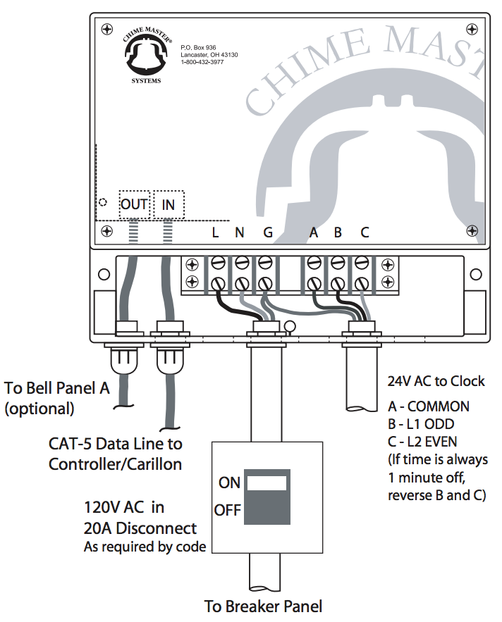
Clock wiring 34DMI24: Difference between revisions
(clock cable specification) |
(Clock movement - corrected output diagram labels) |
||
| Line 27: | Line 27: | ||
;L1 | ;L1 | ||
:This is the 24VAC odd minute input ( | :This is the 24VAC odd minute input (B output on the hookup diagram) | ||
;L2 | ;L2 | ||
:This is the 24VAC even minute input ( | :This is the 24VAC even minute input (C output on the hookup diagram) | ||
;COM | ;COM | ||
:Common is the return current for L1 and L2 ( | :Common is the return current for L1 and L2 (A terminal on the hookup diagram) | ||
Connect the clock with suitable cable (typically 16 AWG Belden 5202UE) to the controller output terminals. | Connect the clock with suitable cable (typically 16 AWG Belden 5202UE) to the controller output terminals. | ||
Revision as of 15:34, 21 November 2019
- Part numbers
- 2034D-MI-24 - For 2206 bell control heads
- 2134D-MI-24 - For carillons and musical bell controls
This clock control panel provides 24VAC Minute Impulse signals to compatible clock movements.
Connections
Power requirements
- Input voltage
- 120 VAC
Power may be supplied either with a power cord plugged into a 120VAC socket or via conduit from the breaker box.
Data connections
One or two RJ jacks for a CAT5 type data cable are on the circuit board at the left side of the control box.
A single jack is provided when tower bells are not used. The cable from this jack goes to the Tower Control output of the Chime Master controller/carillon.
Two jacks are installed when the controller is used with a bell control panel. The right hand jack goes to the controller/carillon and the left hand jack daisy chains the data to the tower bells panel.
Clock movement
The clock movement inputs are generally labeled as follows:
- L1
- This is the 24VAC odd minute input (B output on the hookup diagram)
- L2
- This is the 24VAC even minute input (C output on the hookup diagram)
- COM
- Common is the return current for L1 and L2 (A terminal on the hookup diagram)
Connect the clock with suitable cable (typically 16 AWG Belden 5202UE) to the controller output terminals.
Testing
New installations will be installed with the clock hands pointing straight up. When upgrading an existing clock system you can set the carillon/controller to the position of the dial hands.
On the controller, navigate to the System Setup Menu: Set System Clock menu and press ENTER. If the time displayed is correct, press CANCEL.
The next screen should say: Tower Clock Dial Hands Indicate: 12:00.
Use the cursor buttons to adjust the time to match what the hands are pointing to, then press ENTER.
The hands will move fast to catch up to the current time
If the dial is one minute off
If the system can not adjust the clock to the exact minute, then the Odd and Even outputs are reversed. There are jumpers on the movement to correct this, but it may be easier to reverse the two output wires in the controller.
