Connect tower relays AX: Difference between revisions
mNo edit summary |
mNo edit summary |
||
| Line 1: | Line 1: | ||
[[File:Cat5ax.png | [[File:Cat5ax.png|class=fullwidth|AX Tower relay cable]] | ||
A twisted pair data cable is required and typically we use a minimum of CAT5 with an RJ45 termination at the tower end, and a removable screw terminal at the control head. | A twisted pair data cable is required and typically we use a minimum of CAT5 with an RJ45 termination at the tower end, and a removable screw terminal at the control head. | ||
Revision as of 16:14, 12 March 2021
A twisted pair data cable is required and typically we use a minimum of CAT5 with an RJ45 termination at the tower end, and a removable screw terminal at the control head.
Carillon connection
The pinout of the control head output is as follows (left to right):
1 Blue/White - Status +
2 Blue solid - Status -
3 Brown (both wires) - 12V IN +
4 Orange (both wires) - 12V IN -
5 Green/White - Data +
6 Green solid - Data -
Relay panel connection
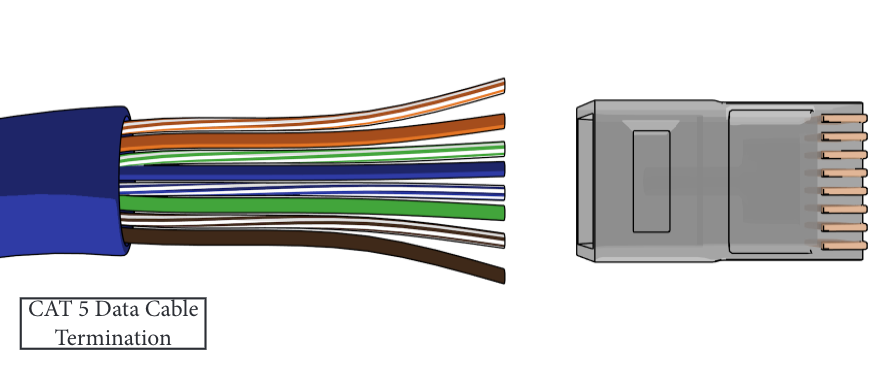
The pinout of the relay panel and wire colors is the standard B style pin out. The following colors appear top to bottom when cable exits the housing to the left and the clip is away from you:
1 Orange/White - 12VDC negative
2 Orange solid - 12VDC negative
3 Green/White - Data A (RS485)
4 Blue solid - Status B (RS485)
5 Blue/White - Status + (RS485)
6 Green solid - Data B (RS485)
7 Brown/White - 12VDC positive
8 Brown solid - 12VDC positive
Crimping Procedure
- Cut cable to length
- Strip 1-1/2" of outer jacket from cable without nicking conductors.
- Pull the jacket back from the end as much as possible.
- Fan-out conductor pairs, orange top, green, blue brown bottom.
- Untwist green, arrange green/white above blue, solid green below.
- Untwist blue, orient solid above blue/white
- Untwist orange and brown pairs, keep solids below the striped.
- Flatten the fan and bring together keeping the order shown above.
- Use scissors to cut the conductors about 3/4" from jacket.
- Double check wire order and insert conductors fully into the RJ45 connector as shown.
- Crimp the connector using an RJ45 crimping tool.
- Inspect the crimp. The wires should be fully inserted and their ends visible at the end of the connector. The gold pins should be recessed in the slots (not protruding above the plastic).
Also see

