Libertas bell control hookup: Difference between revisions
(Hookup - cat5 procedure) |
mNo edit summary |
||
| (30 intermediate revisions by 2 users not shown) | |||
| Line 1: | Line 1: | ||
<div style="font-size:84%">'''[http://www.ChimeMaster.com Home] > [[Chime_Master_Help|Help]] > [[ | <div style="font-size:84%">'''[http://www.ChimeMaster.com Home] > [[Chime_Master_Help|Help]] > [[:Category:Installation|Installation]]'''</div><br /> | ||
=== Equipment and locations === | |||
Generally we provide three types of equipment to install in different areas of the facility. | |||
* [[Libertas_master_clock_controller|Libertas master clock controller]] | ==== User controls ==== | ||
* [[Libertas_master_clock_controller|Libertas master clock controller specification]] | |||
The control panel, sometimes referred to as a master clock, head unit, and may be an electronic carillon is usually located in a sacristy or office area. Many times to save long wiring runs, it may be installed in a balcony area near the tower. In all cases, no ladders should need to be used to access the control panel. | |||
==== Relay panels ==== | |||
High current switching should be as near the bells as practical. The weather resistant relay panels are, in most cases, installed in an enclosed tower chamber below the bells. Precision intelliSwing motor control panels should be within sight of swinging bells for ease of programming. | |||
To prevent moisture from accumulating in the panels, always route conduit to the bottom of the boxes. '''NEVER''' penetrate the top surface of a relay panel. | |||
'' | Specific Relay Model Technical Data: | ||
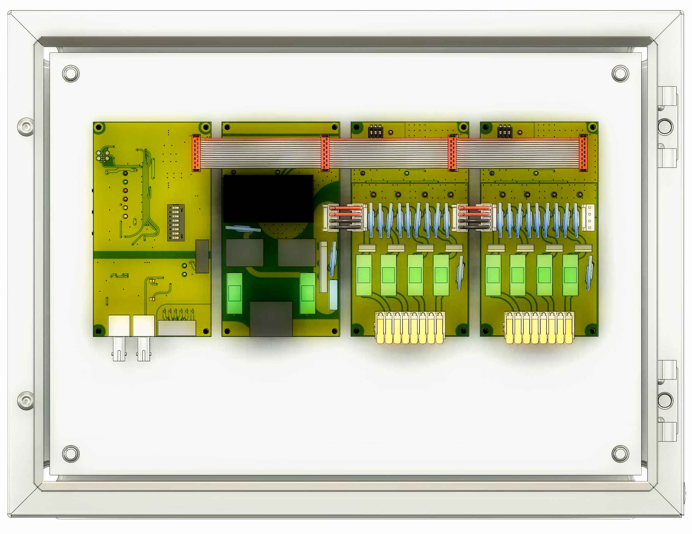
* ''New'' [[Bell Control Technical Data 3700|Libertas 3700 Technical Data]] | |||
[[File:3700T8.jpg|250px|link=Bell Control Technical Data 3700|Bell Control Technical Data 3700]] | |||
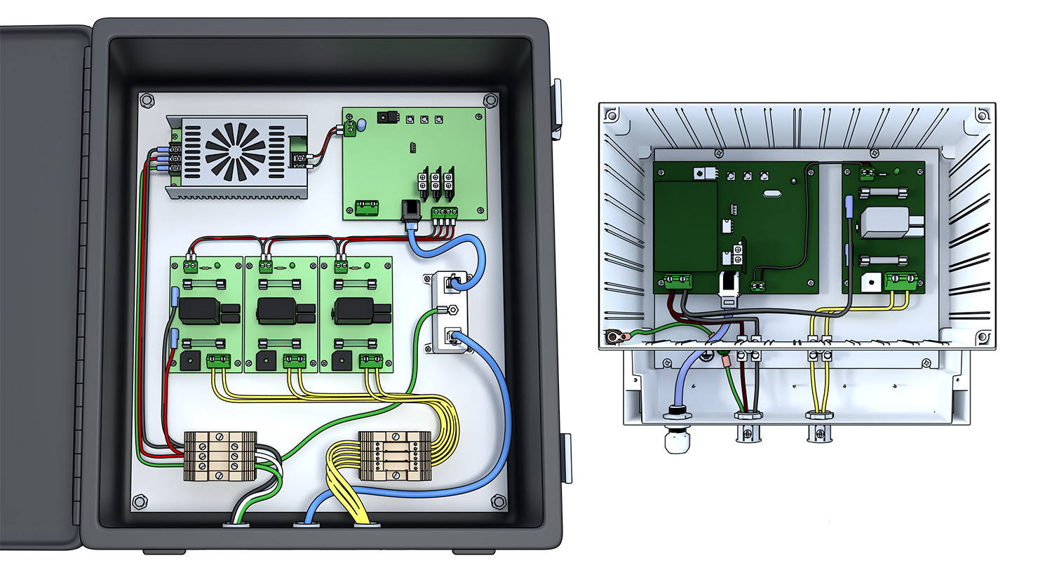
* [[Bell Control Technical Data 2034|Libertas 2034 Technical Data]] | |||
= | [[File:2034RelayPanels.jpg|250px|link=Bell Control Technical Data 2034|Libertas 2034 Technical Data]] | ||
==== Mechanical actuators ==== | |||
Tolling hammers, clappers and swinging motors are installed on the bells themselves and are usually supplied with at least an 18 inch pigtail. Junction boxes need to be located near enough to the actuator to allow connections. Flexible conduit is helpful to allow junction boxes to be re-located during the equipment installation. Separate low current conduits should be provided for swinging motor motion feedback signals (generally 12VDC logic signals). | |||
Bells are always numbered from the largest (bell 1) to the smallest. | |||
For swinging bells, the wheel side of the bell is where the swinging motor will be installed, and a tolling hammer will always be located on the opposite side from the wheel. | |||
Stationary bells can have either outside tolling hammers or inside clappers. The electro-mechanical and physics aspects of this choice generally is made on the basis of how loud the bell is intended to ring. Gravity favors outside hammers helping the power of the striking of the bell. Gravity works against inside clappers resulting in a softer tone. Visual esthetics aside, choose clappers for musical instruments and hammers for tolling bells. | |||
[[Category:Installation]] | [[Category:Installation]] | ||
[[Category:Troubleshooting]] | |||
Latest revision as of 14:27, 9 October 2023
Equipment and locations
Generally we provide three types of equipment to install in different areas of the facility.
User controls
The control panel, sometimes referred to as a master clock, head unit, and may be an electronic carillon is usually located in a sacristy or office area. Many times to save long wiring runs, it may be installed in a balcony area near the tower. In all cases, no ladders should need to be used to access the control panel.
Relay panels
High current switching should be as near the bells as practical. The weather resistant relay panels are, in most cases, installed in an enclosed tower chamber below the bells. Precision intelliSwing motor control panels should be within sight of swinging bells for ease of programming.
To prevent moisture from accumulating in the panels, always route conduit to the bottom of the boxes. NEVER penetrate the top surface of a relay panel.
Specific Relay Model Technical Data:
Mechanical actuators
Tolling hammers, clappers and swinging motors are installed on the bells themselves and are usually supplied with at least an 18 inch pigtail. Junction boxes need to be located near enough to the actuator to allow connections. Flexible conduit is helpful to allow junction boxes to be re-located during the equipment installation. Separate low current conduits should be provided for swinging motor motion feedback signals (generally 12VDC logic signals).
Bells are always numbered from the largest (bell 1) to the smallest.
For swinging bells, the wheel side of the bell is where the swinging motor will be installed, and a tolling hammer will always be located on the opposite side from the wheel.
Stationary bells can have either outside tolling hammers or inside clappers. The electro-mechanical and physics aspects of this choice generally is made on the basis of how loud the bell is intended to ring. Gravity favors outside hammers helping the power of the striking of the bell. Gravity works against inside clappers resulting in a softer tone. Visual esthetics aside, choose clappers for musical instruments and hammers for tolling bells.